Connecting the antenna on the PCB board
Introduction
When it comes to designing a printed circuit board (PCB) that includes wireless communication capabilities, incorporating an antenna into the PCB layout is an important consideration. The antenna is what allows your device to send and receive radio frequency (RF) signals, so it is critical that it be carefully designed and placed in the correct location on the PCB. In this article, we’ll cover the basics of how to add an antenna to your PCB and ensure that it is properly connected.
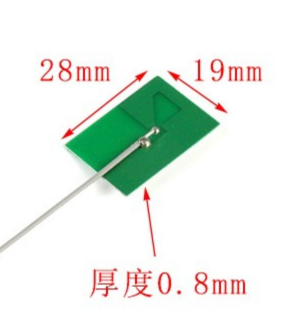
Selecting an Antenna
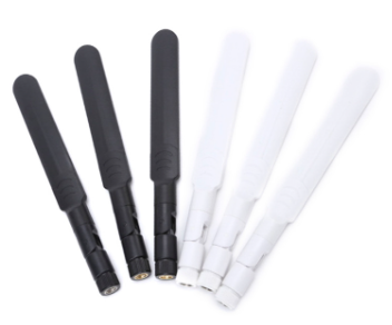
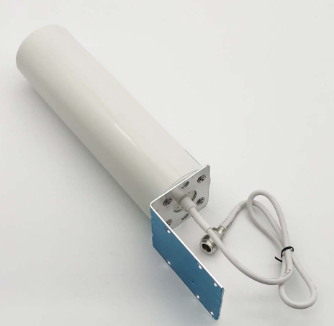
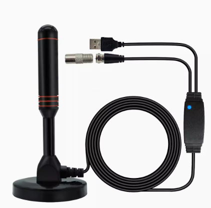
Before you start designing your PCB with an antenna, you need to choose the right type of antenna for your application. There are many different types of antennas, including wire antennas, patch antennas, and printed antennas. The type you choose will depend on your application requirements, such as the frequency range you need to operate in, the size of your PCB, and the amount of power you need to transmit. Once you have selected an antenna, you will need to incorporate it into your PCB design.
Designing the Antenna
When designing your PCB with an antenna, there are a few key considerations to keep in mind:
1. Select the Correct Material - Depending on your requirements, you may need to select a specific dielectric constant and material for your PCB. These factors can impact the performance of your antenna and its ability to effectively radiate and receive RF signals.
2. Placement - The placement of your antenna is also critical. In general, you want the antenna to have a clear path to the outside world, so it is important to orient the antenna in the right direction and ensure that there are no obstructions in the way.
3. Ground Plane - The ground plane is an important part of your antenna design because it can help to enhance the radiation pattern of your signal. You want to ensure that your antenna is properly grounded and that there is a sufficient ground plane on your PCB for optimal performance.
Connecting the Antenna
Once you have designed your antenna and incorporated it into your PCB, it’s time to connect it to the rest of the circuit. There are a few different ways to connect an antenna to a PCB, depending on the type of antenna you are using and the requirements of your application. Here are some basic guidelines:
1. Coaxial Cable - A coaxial cable is a common way to connect an antenna to a PCB. You simply solder the center conductor of the coaxial cable to the antenna feed point, and then connect the outer conductor to the ground plane. This can be a good option if you need to connect your antenna to an external RF module.
2. Soldering - If you are using a wire antenna or a printed antenna, you may be able to simply solder it directly to the PCB. Ensure that there is a good electrical connection between the antenna and the PCB.
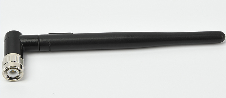
3. Connector - Another option is to use an RF connector to attach your antenna to your PCB. This can be a good option if you need to change out antennas frequently or if you want to keep your antenna detached from your PCB during testing.
Conclusion
In summary, integrating an antenna into your PCB design requires careful consideration of many factors. These include selecting the correct antenna type, designing the antenna properly, and connecting the antenna to the rest of the circuit. By following these guidelines, you can ensure that your PCB is equipped to transmit and receive RF signals effectively.
